The MAX6956 and MAX6957 are versaTIle 28-segment LED display drivers which allow any of the outputs to be configured as general purpose inputs/outputs (GPIO). Control is made through a high-speed SPI™ (MAX6957) or I²C (MAX6956) serial interface.
This applicaTIon note describes a utility program which allows a MAX6957 or MAX6956 driver to be controlled from a PC. The utility can be used as a standalone to help an engineer become familiar with the registers and functions of the drivers. Moreover, it can be used to 'prove' an application board prototype by directly controlling the MAX6957 or MAX6956 registers before the equipment's software is designed.
Requirements
A PC running Windows® 95, 98, 98SE, ME, NT, or 2000 with a parallel printer port configured for either LPT1 or LPT2.Description
The utility is a Visual Basic 5 program called MAX6957.EXE which requires the standard Visual Basic run time library MSVBVM50.DLL in order to run at all. The program uses the DriverLINX™ freeware parallel port driver DLPortIO.DLL which provides the Win32 DLL hardware I/O functions not available as standard in Visual Basic. Windows NT and 2000 users also require the DLPortIO.SYS kernel mode driver. Both of these drivers are copyright Scientific Software Tools, Inc. (http://www.driverlinx.com).Installation
To install to a Windows 95, 98, 98SE, ME platform, download the MAX6956-57.EXE file. This is a WinZIP self-extracting archive that contains ReadMe.txt, ReadMeSST.txt, MAX6957.EXE, DLPortIO.DLL, and MSVBVM50.DLL. The default download directory is C:\MAX6956. MSVBVM50.DLL may be deleted if the library is already registered on the computer.To install to a Windows NT or 2000 platform, download the MAX6956-NT.EXE file. This is a WinZIP self-extracting archive that contains ReadMe.txt, ReadMeSST.txt, MAX6956.EXE, PORT95NT.EXE, and MSVBVM50.DLL. The default download directory is C:\MAX6956. PORT95NT.EXE is the install program for the DriverLINX drivers which installs and registers the DLPortIO.DLL library and DLPortIO.SYS driver. PORT95NT.EXE can be deleted after installation. Windows 95, 98, 98SE, ME users can also use this installation procedure if they wish.
Source Code
The source code for this application note is available at http://www.maxim-ic.com/products/display/software/.Connecting a MAX6956 or MAX6957 to the Parallel Port
This utility uses 3 of the 8 parallel port printer output lines to simulate SPI serial interface activity, and another 2 output lines to simulate I²C serial interface activity. Parallel port control input lines are used to read back SPI data, I²C data, and interrupt status. Multiple (up to 16, daisy-chained) MAX6957s and/or multiple (up to 16, configured with different I²C addresses) MAX6956s may be operated at once. Either the LPT1 or LPT2 port may be selected from the software. The port can be a standard, ECP, or EPP type. The port connections are shown in Figure 1.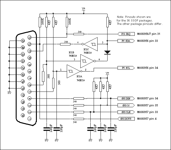
Figure 1. The MAX6956 and MAX6957 connections to the parallel port.
The program brings up 4 windows on startup. These are the main control, intensity control, I/O control, and segment control windows. The register settings on start-up mirror the register power-up conditions of the MAX6956 and MAX6957.
The main control is shown in Figure 2 below. The 'Driver type' radio buttons select whether the software will transmit to MAX6957 (using the SPI connection) or the MAX6956 (using the I²C connection).
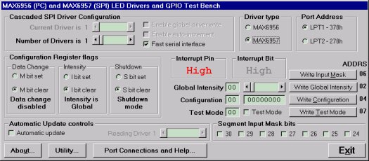
Figure 2. Program display on startup.
In SPI mode, the software controls up to 16 MAX6957 drivers. The drivers are presumed to be cascaded, (i.e., the DOUT pin of the first MAX6957 connects to the DIN pin of the second MAX6957, whose DOUT pin connects to the DIN pin of the third MAX6957, and so on). The total number of MAX6957 devices is set by the 'Number of Drivers' slider. When this is set to more than 1, the 'Enable global driver write' and 'Enable auto-increment' check boxes are available. When 'Enable global driver write' is clear, only the MAX6957 driver selected by the 'Current Driver' slider is written to when a write command is selected - the others receive the no-op instruction. When 'Enable global driver write' is checked, all the MAX6957 drivers are written to with the same data. When 'Enable auto-increment' is checked, the current driver number is automatically incremented after each write action. This allows the user to quickly send the same data for a series of MAX6957 drivers.
The SPI interface connection to the parallel port can be tested with the 'Test Stream' facility which can be found under 'Port Connections and Help...' when the program is running. The 'Test Stream' facility transmits the no-op instruction continuously to the MAX6957(s) (as set by the 'Number of Drivers' slider) allowing the interface connections to be verified without affecting register contents.
In I²C mode, the software controls up to 16 MAX6956 drivers. The first driver is presumed to be set to address 1000000x, with the addresses of subsequent devices increasing to 1001111x for the last device. To access, for example, a single MAX6956 driver at address 1001111x, simply set the 'Number of Drivers' slider to 16 and then the 'Current Driver' slider to 16, address 1001111x. The main form in I²C mode is shown in Figure 3.
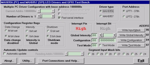
Figure 3. I²C program display.
The I²C interface connection to the parallel port can be tested with the 'Test Stream' facility which can be found under 'Port Connections and Help...' when the program is running. The 'Test Stream' facility transmits the no-op instruction continuously to all MAX6956(s) (as set by the 'Number of Drivers' slider) allowing the interface connections to be verified without affecting register contents.
The 'Fast serial interface' check box sets the serial interface speed for both SPI and I²C interface types. When checked, serial interface runs at machine-dependent full speed up to 1 Mbits/sec; unchecked, the speed is limited to 500 bits/sec maximum. The slow speed may be useful when connecting over very long cables.
The program will normally only communicate with the target driver (or drivers) when a 'Write' or 'Read' button is pressed. However, the program attempts to monitor an interrupt output pin presumed to be connected to the parallel port pin 13. This is displayed on the main window and displays status as High or Low.
The 'Automatic Update control' button, when checked, makes the program continually poll all 28 port input registers and the interrupt register bit. The reading rate depends on the setting of the 'Fast serial interface' check box, and is many times a second (Fast) or every many seconds (Slow). Note: slow mode is very slow! The 'Reading driver x' slider allows the user to set the device being automatically read independently to the driver(s) accessible through the 'Current driver' control.
The main window is the route to Exit the program. The Exit button, or pressing the Esc key on the main window, closes all 4 windows. Pressing the Esc key in one of the other 3 windows takes the user to the main window; therefore, pressing the Esc key twice will close the program quickly. Before closing, the program stores the last settings for device configuration in a file called MAX6956.ini in the same directory that the program was executed from. Nothing is written to Windows registry. The settings includes the positions of the 4 windows, and the interface settings on the main window. If the MAX6956.ini doesn't exist then it is created; otherwise it is overwritten. To restore program default settings, or if the MAX6956.ini is corrupted, simply delete the MAX6956.ini file.
Figures 4, 5, and 6 show snapshots of the other three windows.
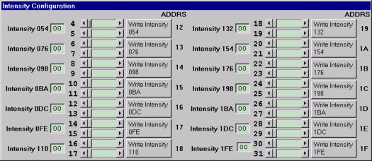
Figure 4. Intensity configuration window.
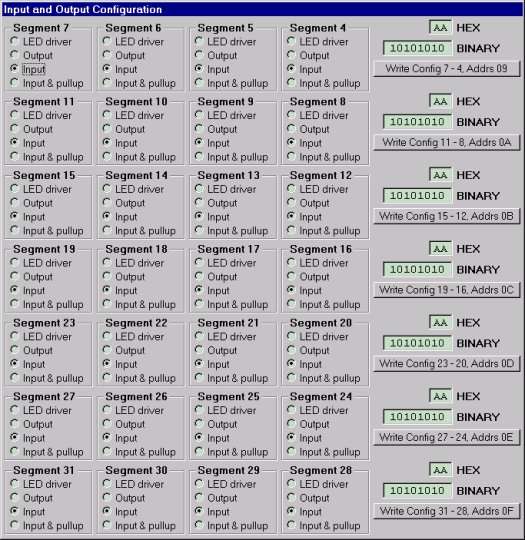
Figure 5. I/O configuration window.
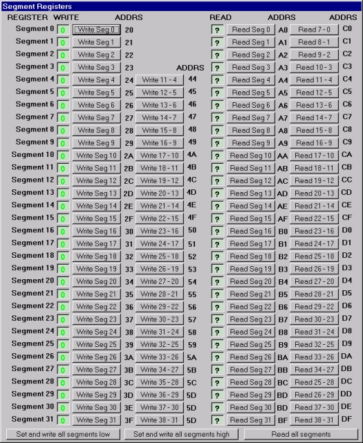
Figure 6. Segment registers window.
DriverLINX is a trademark of Scientific Software Tools, Inc.
SPI is a trademark of Motorola, Inc.
Windows is a registered trademark of Microsoft Corp.